


 PURPOSE AND SCOPE OF APPLICATION
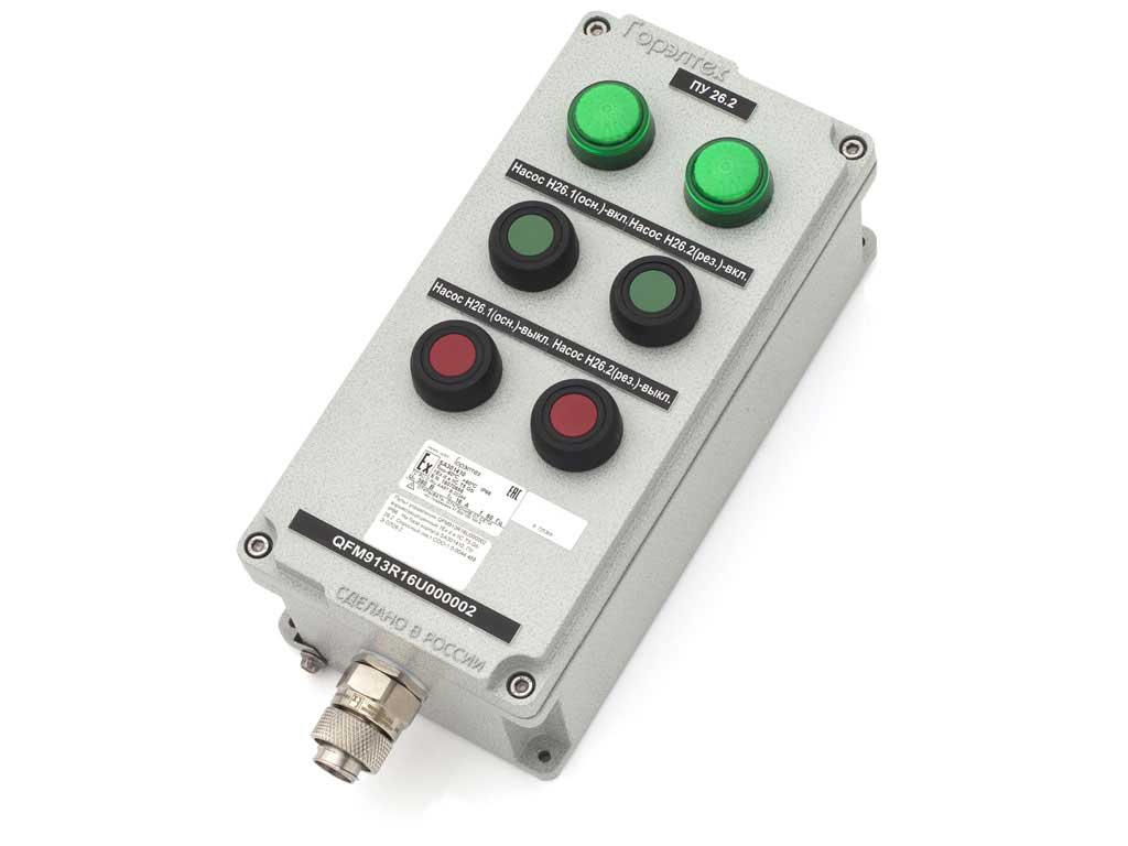
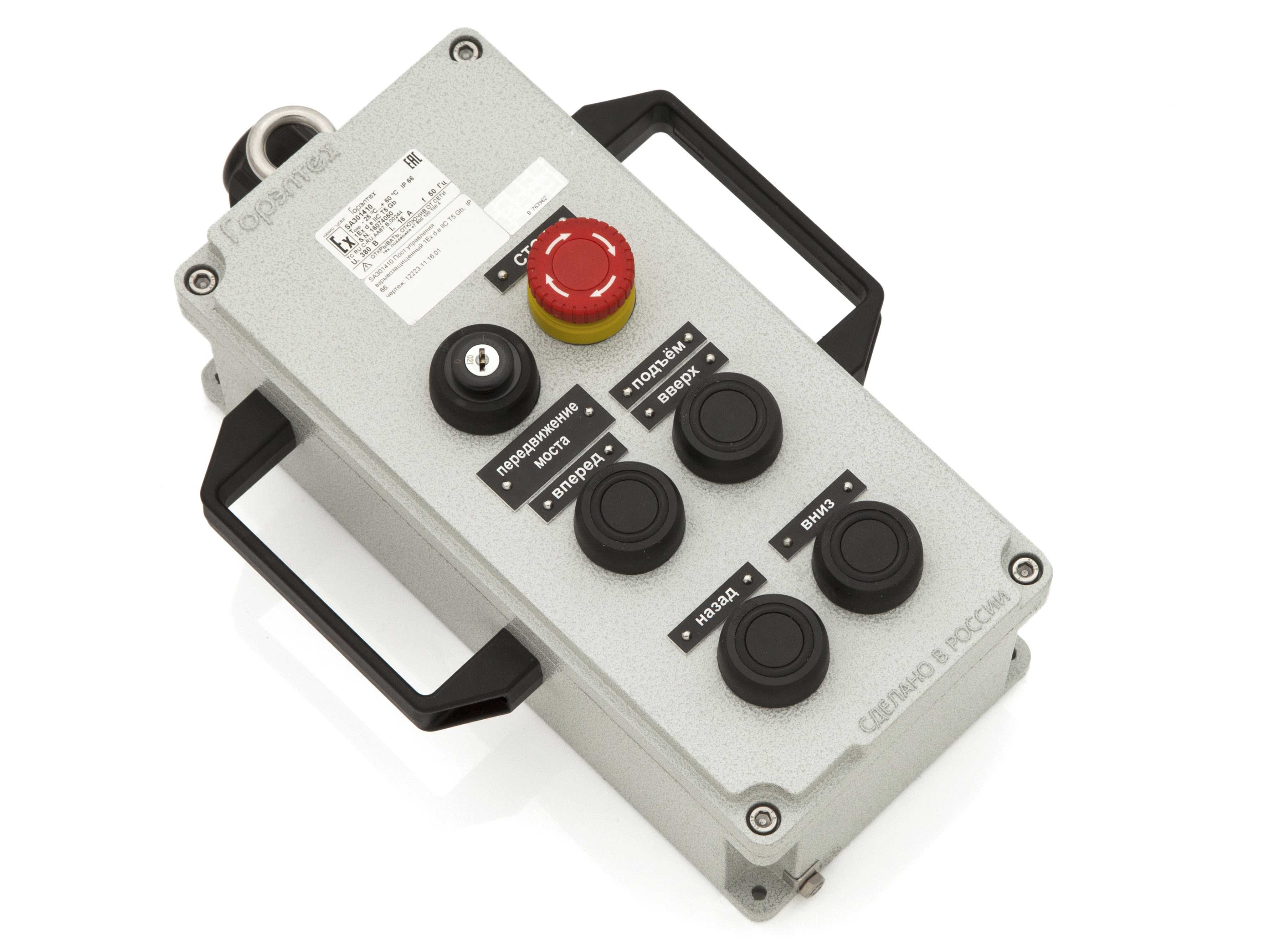
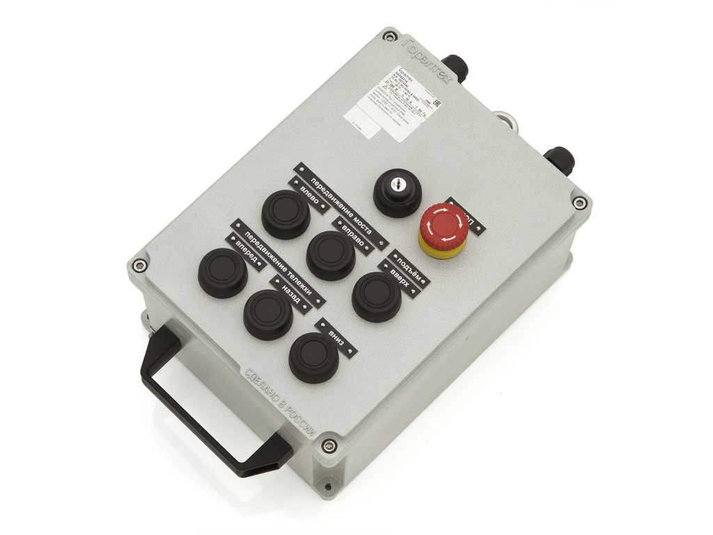
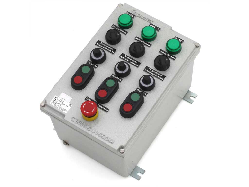
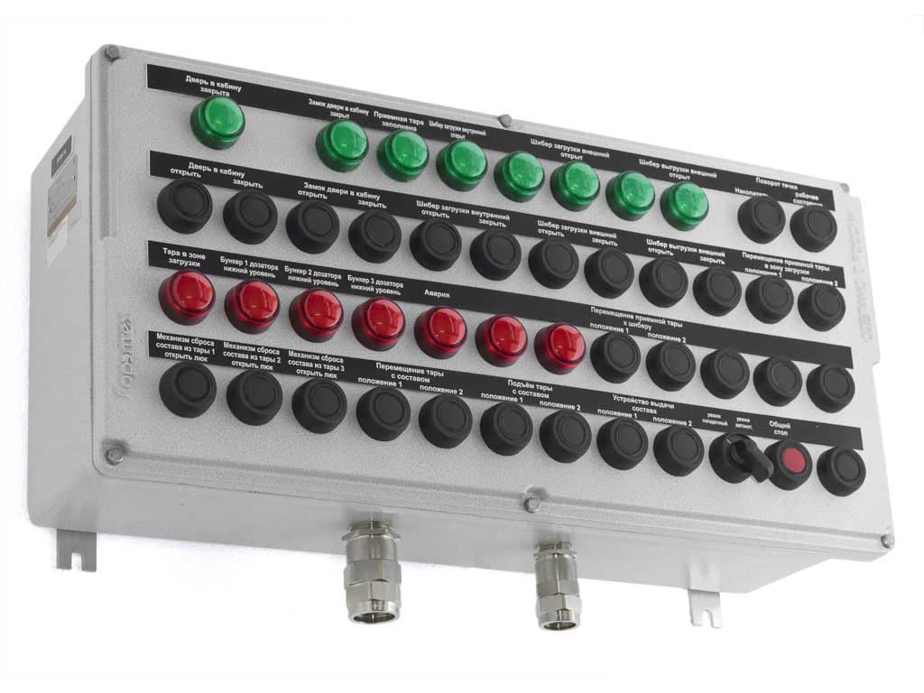
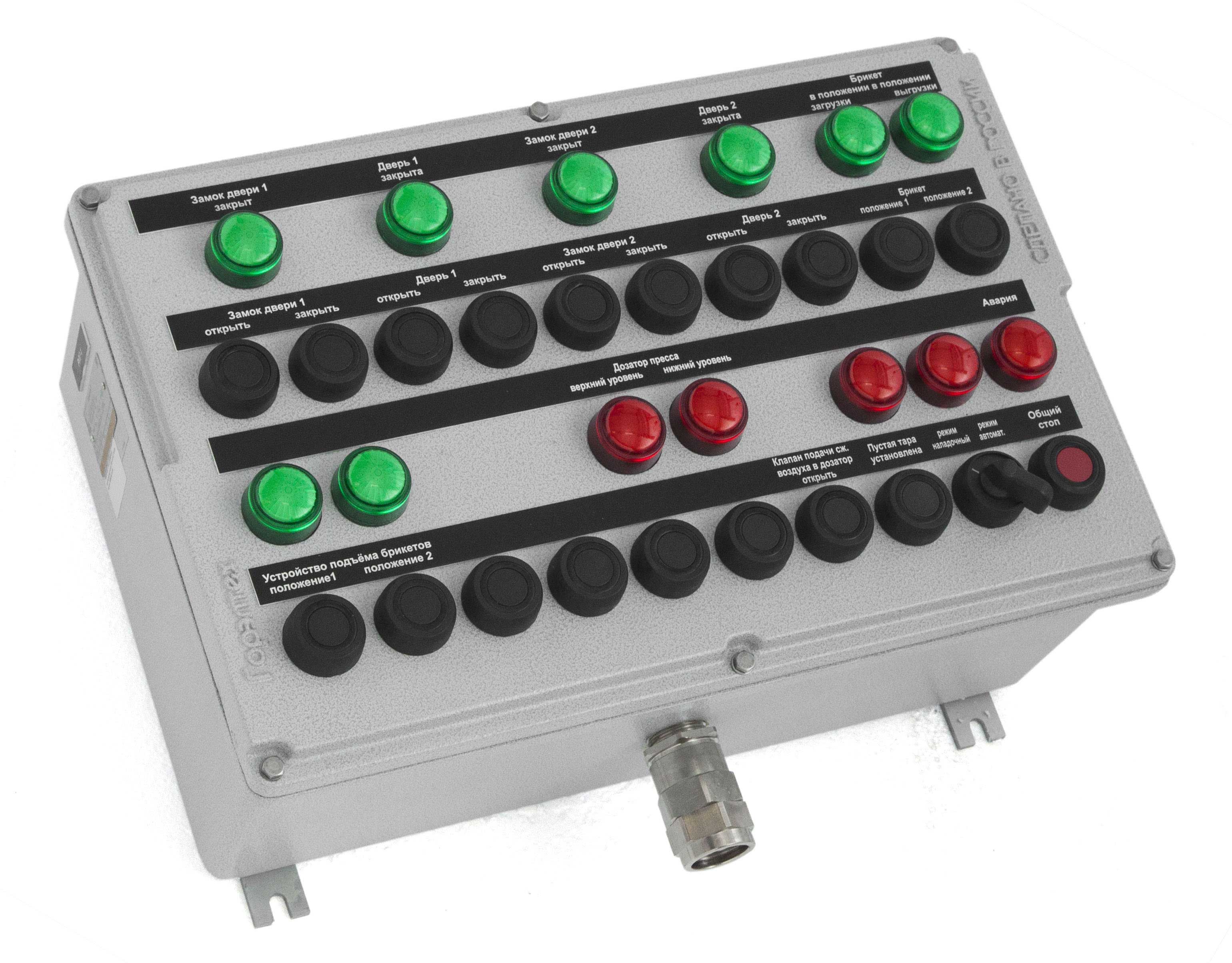
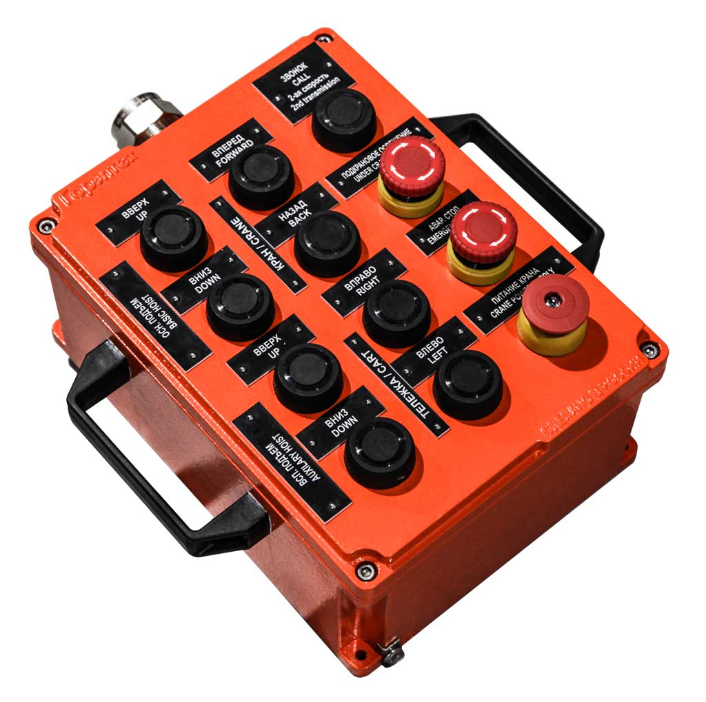
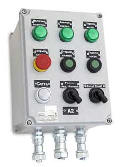
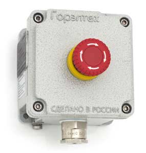
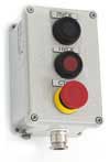
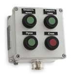
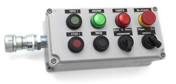
 Explosion-proof local control stations and indicating devices PKIE are used in oil-and-gas, chemical, pharmaceutical and food industry, in metallurgy, power industry etc. Explosion-proof local control stations series PKIE are intended for control of various mechanisms and devices (pumps, fans, stirring machines etc.) Flexible modular system of local control stations is reached by application of different dimension types of enclosures and various control and indicating modules. One of the main advantages of local control stations is PKIE right colors of visual part of control and indicating modules, i.e. buttons, lamps and other. Control and indicating elements and cable glands are installed as per customer‘s requirements.
Information labels for buttons and signal lamps are manufactured upon customer‘s request.
Full production cycle starting from casting molds and to ready product is performed at the explosion-proof equipment plant “ZAVOD GORELTEX” Co. Ltd. on the territory of the Russian Federation.
Scope of application - hazardous indoor and outdoor areas and mines non-hazardous with gas or dust in accordance with explosion protection marking, GOST 30852.13-2002 (IEC 60079-14:1996) that regulates application of electrical equipment in hazardous and non-hazardous areas and dangerous production facilities of I, II, III, IV hazard classes under supervision of Rostekhnadzor and national supervisory bodies of the CIS countries.
 1Ex db e IIC T6...T4 Gb 1Ex db e mb IIC T6...T4 Gb Ex tb IIIC T85°C...135°C Db Ex ia IIIC T85°C...135°C Da
 ЕАЭС RU C-RU.НА67.В.00163/21
 ЕАЭС RU C-RU.МЛ02.В.00298/20
 РОСС RU С-RU.МЮ62.В.00097/23
 ГОСТ Р ИСО 9001-2015 (ISO 9001:2015)
 RU.ОС ВССТ 0116-10.2020
 IECEx CCVE 19.0002X IECEx CCVE 18.0013U
 EESF 19 ATEX 012U EESF 19 ATEX 053X
 ЕАЭС RU С-RU.ПБ74.В.00152/20 ЕАЭС RU С-RU.ПБ74.В.00090/20
 ТУ 3400-005-72453807-07 ТУ 27.12.31-037-72453807-2017
 ОГН4.RU.1104.В01557
 KZ39VEH00005608 РОСС RU.ФБ01.Н0006923
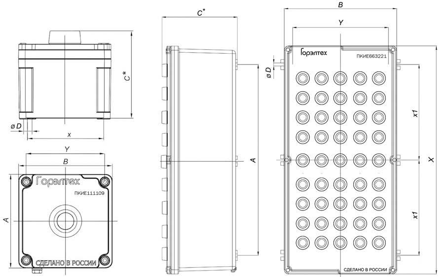
Dimension type of enclosure |
Max. quantity of control and indicating elements on enclosure cover* |
Dimensions, mm | Mass of enclosure, kg | ||||||
| outer | mounting | ||||||||
| A | B | C | X | X1 | Y | ØD | |||
| PKIE111109 | 1 | 112 | 112 | 91 | 94 | - | 94 | 6,3 | 0,8 |
| PKIE171109 | 3 | 172 | 112 | 91 | 154 | - | 94 | 6,3 | 1,1 |
| PKIE141410 | 4 | 149,5 | 149,5 | 107 | 131 | - | 131 | 6,3 | 1,4 |
| PKIE202012 | 6 | 201 | 201 | 129 | 180 | - | 180 | 6,5 | 2,5 |
| PKIE301410 | 8 | 304,5 | 149,5 | 109 | 285 | - | 131 | 6,3 | 2,4 |
| PKIE302314 | 15 | 305 | 231 | 140 | 285 | - | 211 | 6,3 | 3,9 |
| PKIE342421 | 16 | 348 | 243 | 212 | 255 | - | 250 | 9 | 8,9 |
| PKIE513321 | 35 | 511 | 336 | 207 | 418 | - | 330 | 9 | 15 |
| PKIE663221 | 45 | 669 | 329 | 207 | 576 | 288 | 332 | 9 | 18,7 |
| PKIE626221 | 95 | 622 | 622 | 208 | 530 | 265 | 616 | 9 | 29,5 |
* Quantity of installed elements depends on their dimensions and typical dimension sizes of contact blocks. Exact quantity of the elements and dimension type of enclosure for a specific solution is determined during making an order. Production of modular explosion-proof local control stations according to customer’s specification is possible.
| Type | Picture | Drawing |
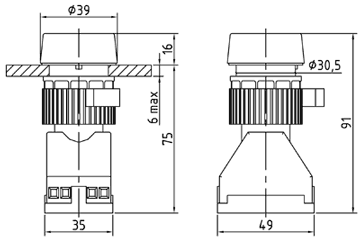
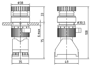
| LGE03... | 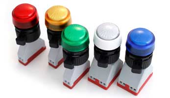 |
Blue White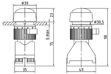 |
Red Green Yellow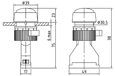 |
| Type | Color | Rated voltage, V | Power consumption, W |
| LGE03K12 | Red | ~/ 12 12 |
>max. 1 |
| LGE03Z12 | Green | ||
| LGE03ZH12 | Yellow | ||
| LGE03S12 | Blue | ||
| LGE03B12 | White | ||
| LGE03K24 | Red | ~/16-36 |
|
| LGE03Z24 | Green | ||
| LGE03ZH24 | Yellow | ||
| LGE03S24 | Blue | ||
| LGE03B24 | White | ||
| LGE03K220 | Red | ~220-380 | |
| LGE03Z220 | Green | ||
| LGE03ZH220 | Yellow | ||
| LGE03S220 | Blue | ||
| LGE03B220 | White |
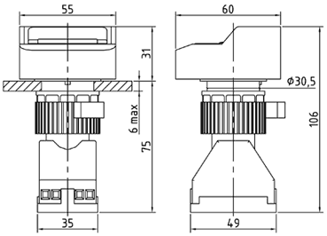
| Type | Picture | Drawing |
| KGE01... |  |
 |
| KGE10... |  |
 |
| Type | Contacts | Color | Rated voltage, V | Rated current, А |
| KGE01K11 | 1NO+1NC | Red | ~120 ~220 ~380 1224110250 |
16 (at ~120 V) 10 (at ~220 V) 6 (at ~380 V) 2 (at 12 V)2 (at 24 V)1 (at 110 V)0,5 (at 250 V) |
| KGE01K20 | 2NO | |||
| KGE01K02 | 2NC | |||
| KGE01K40 | 4NO | |||
| KGE01K31 | 3NO+1NC | |||
| KGE01K22 | 2NO+2NC | |||
| KGE01K13 | 1NO+3NC | |||
| KGE01K04 | 4NC | |||
| KGE01Z11 | 1NO+1NC | Green | ||
| KGE01Z20 | 2NO | |||
| KGE01Z02 | 2NC | |||
| KGE01Z40 | 4NO | |||
| KGE01Z31 | 3NO+1NC | |||
| KGE01Z22 | 2NO+2NC | |||
| KGE01Z13 | 1NO+3NC | |||
| KGE01Z04 | 4NC | |||
| KGE01ZH11 | 1NO+1NC | Yellow | ||
| KGE01ZH20 | 2NO | |||
| KGE01ZH02 | 2NC | |||
| KGE01ZH40 | 4NO | |||
| KGE01ZH31 | 3NO+1NC | |||
| KGE01ZH22 | 2NO+2NC | |||
| KGE01ZH13 | 1NO+3NC | |||
| KGE01ZH04 | 4NC | |||
| KGE01S11 | 1NO+1NC | Blue | ||
| KGE01S20 | 2NO | |||
| KGE01S02 | 2NC | |||
| KGE01S40 | 4NO | |||
| KGE01S31 | 3NO+1NC | |||
| KGE01S22 | 2NO+2NC | |||
| KGE01S13 | 1NO+3NC | |||
| KGE01S04 | 4NC | |||
| KGE01B11 | 1NO+1NC | White | ||
| KGE01B20 | 2NO | |||
| KGE01B02 | 2NC | |||
| KGE01B40 | 4NO | |||
| KGE01B31 | 3NO+1NC | |||
| KGE01B22 | 2NO+2NC | |||
| KGE01B13 | 1NO+3NC | |||
| KGE01B04 | 4NC | |||
| KGE01CH11 | 1NO+1NC | Black | ||
| KGE01CH20 | 2NO | |||
| KGE01CH02 | 2NC | |||
| KGE01CH40 | 4NO | |||
| KGE01CH31 | 3NO+1NC | |||
| KGE01CH22 | 2NO+2NC | |||
| KGE01CH13 | 1NO+3NC | |||
| KGE01CH04 | 4NC | |||
| KGE10K11 | 1NO+1NC | Momentary mushroom button, red | ||
| KGE10K20 | 2NO | |||
| KGE10K02 | 2NC | |||
| KGE10K40 | 4NO | |||
| KGE10K31 | 3NO+1NC | |||
| KGE10K22 | 2NO+2NC | |||
| KGE10K13 | 1NO+3NC | |||
| KGE10K04 | 4NC | |||
| KGE10CH11 | 1NO+1NC | Momentary mushroom button, black |
||
| KGE10CH20 | 2NO | |||
| KGE10CH02 | 2NC | |||
| KGE10CH40 | 4NO | |||
| KGE10CH31 | 3NO+1NC | |||
| KGE10CH22 | 2NO+2NC | |||
| KGE10CH13 | 1NO+3NC | |||
| KGE10CH04 | 4NC |
Version of buttons with gold-plated contacts used for designing of circuits of low current systems - /ST option. Example: KGE01ZH20/ST.
| Type | Picture | Drawing |
| KGE02... |  |
 |
| Type | Contacts | Description | Color | Rated voltage, V |
Rated current, А |
| KGE02KZ11 | 1НО+1НЗ | Momentary double-headed button | Green + red* | ~120 ~220 ~380 1224110250 |
16 (at ~120 V) 10 (at ~220 V) 6 (at ~380 V) 2 (at 12 V)2 (at 24 V)1 (at 110 V)0,5 (at 250 V)
|
| KGE02KZ20 | 2НО | ||||
| KGE02KZ02 | 2НЗ | ||||
| KGE02KZ40 | 4NO | ||||
| KGE02KZ31 | 3NO+1NC | ||||
| KGE02KZ22 | 2NO+2NC | ||||
| KGE02KZ13 | 1NO+3NC | ||||
| KGE02KZ04 | 4NC |
* Buttons with other color combinations may be supplied upon request.
Version of buttons with gold-plated contacts used for designing of circuits of low current systems - /ST option. Example: KGE02KZ20/ST.
| Type | Picture | Drawing |
| KGE06... |  |
 |
| Type | Contacts | Color | Rated voltage of contact block, V | Rated current of contact block, А | Rated voltage of indication, V |
| KGE06K10 | 1NO | Red | ~120 ~220 ~380 1224110250 |
10 (at ~120 V) 10 (at ~220 V) 6 (at ~380 V) 2 (at 12 V)2 (at 24 V)1 (at 110 V)0,5 (at 250 V) |
24-48 ~24-240 |
| KGE06K01 | 1NC | ||||
| KGE06Z10 | 1NO | Green | |||
| KGE06Z01 | 1NC | ||||
| KGE06ZH10 | 1NO | Yellow | |||
| KGE06ZH01 | 1NC | ||||
| KGE06S10 | 1NO | Blue | |||
| KGE06S01 | 1NC | ||||
| KGE06B10 | 1NO | White | |||
| KGE06B01 | 1NC |
| Circuit diagram for KGE06...10 button | Circuit diagram for KGE06...01 button |
 |
 |
| Type | Picture | Drawing |
| KGE07... | 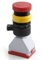 |
|
| KGE08... |  |
 |
| KGE09... | 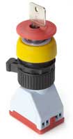 |
 |
| KGE09.../ZSNCH |  |
 |
| Type | Contacts | Description | Color | Rated voltage, V | Rated current, А |
| KGE07K11 | 1NO+1NC | locking mushroom button, unclocking by rotation | Red | ~120 ~220 ~380 1224110250 |
16 (at ~120 V) 10 (at ~220 V) 6 (at ~380 V) 2 (at 12 V)2 (at 24 V)1 (at 110 V)0,5 (at 250 V)
|
| KGE07K20 | 2NO | ||||
| KGE07K02 | 2NC | ||||
| KGE07K40 | 4NO | ||||
| KGE07K31 | 3NO+1NC | ||||
| KGE07K22 | 2NO+2NC | ||||
| KGE07K13 | 1NO+3NC | ||||
| KGE07K04 | 4NC | ||||
| KGE08K11 | 1NO+1NC | locking mushroom button, unclocking by rotation | Red, with yellow bezel |
||
| KGE08K20 | 2NO | ||||
| KGE08K02 | 2NC | ||||
| KGE08K40 | 4NO | ||||
| KGE08K31 | 3NO+1NC | ||||
| KGE08K22 | 2NO+2NC | ||||
| KGE08K13 | 1NO+3NC | ||||
| KGE08K04 | 4NC | ||||
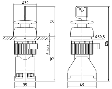
| KGE09K11 | 1NO+1NC | locking mushroom button, key release | Red, with yellow bezel |
||
| KGE09K20 | 2NO | ||||
| KGE09K02 | 2NC | ||||
| KGE09K40 | 4NO | ||||
| KGE09K31 | 3NO+1NC | ||||
| KGE09K22 | 2NO+2NC | ||||
| KGE09K13 | 1NO+3NC | ||||
| KGE09K04 | 4NC |
Version of buttons with gold-plated contacts used for designing of circuits of low current systems - /ST option. Example: KGE08K02/ST.
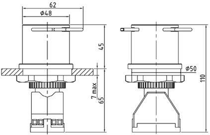
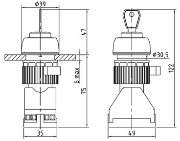
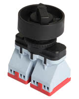
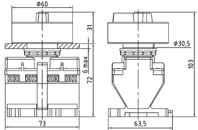
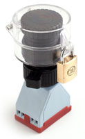
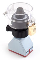
| Type | Picture | Drawing |
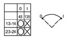
| PGE1C PGE2I PGE1Z PGE1W |
 |
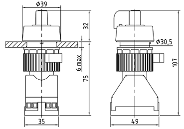 |
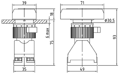
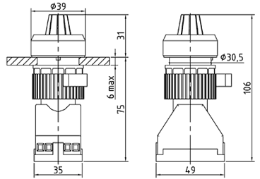
| PGEZ... | 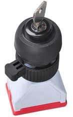 |
 |
| PGE2S PGE4I PGE2Z |
 |
 |
| PGEPKL | 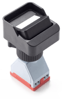 |
 |
| Type | Contacts | Description | Rated voltage, V | Rated current, А |
|
| PGE1C | 2NO | Switch, 3 positions with zero position, diagram 1C |
 |
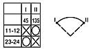
~120 ~220 ~380 1224110250 |
16 (at ~120 V) 10 (at ~220 V) 6 (at ~380 V) 2 (at 12 V)2 (at 24 V)1 (at 110 V)0,5 (at 250 V) |
| PGE2I | 2NO | Switch, 2 positions, diagram 2I |
 |
||
| PGE1Z | 1NO + 1NC | Switch, 2 positions, diagram 1Z |
 |
||
| PGE1W | 2NO | Switch 3 positions, diagram 1W |
 |
||
| PGEZ1S | 2NO | Key operated switch, 3 positions. Key is removed in any position of the switch. Diagram 1C |
|
||
| PGEZ2I | 2NO | Key operated switch, 2 positions. Key is removed in any position of the switch. Diagram 2I |
|
||
| PGEZ1Z | 1NO + 1NC | Key operated switch, 2 positions. Key is removed in any position of the switch. Diagram 1Z |
|
||
| PGEZ1W | 2NO | Momentary key operated switch, 3 positions. Key is removed in the medium position of the switch. Diagram 1W |
|
||
| PGE2S | 4NO | Switch, 3 positions with zero position, diagram 2C |
 |
||
| PGE4I | 4NO | Switch, 2 positions, diagram 4I |
 |
||
| PGE2Z | 2NO + 2NC | Switch, 2 positions, diagram 2Z |
 |
||
| PGEPKL2I | 2NO | Switch, 2 positions, diagram 2I |
 |
||
| PGEPKL1Z | 1NO + 1NC | Switch, 2 positions, diagram 1Z |
 |
||
Version of buttons with gold-plated contacts used for designing of circuits of low current systems - /ST option. Available for types PGE1C, PGE2I, PGE1Z, PGEZ1W. Example: PGE1Z/ST.
| Type | Picture | Drawing |
| PTCE... | 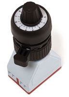 |
 |
| Type | Resistance, Ohm | Power consumption, W |
| PTCE01 | 1 000 | 1 |
| PTCE02 | 2 000 | |
| PTCE03 | 5 000 | |
| PTCE04 | 10 000 |
| Type | Picture | Drawing |
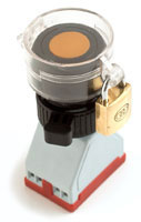
| /ZAMOK1 | 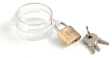 |
 |
| /ZAMOK2 |  |
 |
 |
 |
 |
| Type | Picture | Drawing |
| PSGE01 |  |
 |
| Type | Type of sound signal | Rated voltage, V | Current consumption, А | Sound pressure, dB |
| PSGE01 | Intermittent | 12* |
0,15 | 108 |
* ~220 V version is possible in a ready product.
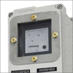
| Type | Picture | Description |
| M-KIP |  |
Ammeter* |
| Voltmeter* |
* Dimension type, scale, accuracy class and measurement range shall be approved when ordering.
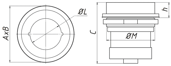
| Name | Dimensions, mm | Mass, kg | |||||
| External | Window size | Hole for installation | |||||
| A | B | C | h | ØL | ØM | ||
| М-KIP-..-48 | 99 | 99 | 107,5 | 27 | 55 | Ø85 | 0,6 |
| М-KIP-..-72 | 139 | 139 | 111,7 | 29,8 | 90 | Ø130 | 1,5 |
| PKIE Х | - | Х | Х | ... | Х | Х | - | Х | Х | ( | Х | ) - | Х | Х | ( | Х | ) / | Х | – TU 3400-005-72453807-07 | ||||
| Dimension type of enclosure | |||||||||||||||||||||||
| Quantity of control and indicating elements | |||||||||||||||||||||||
| Type of control and indicating elements | |||||||||||||||||||||||
| Quantity of cable glands | |||||||||||||||||||||||
| Type of cable gland | |||||||||||||||||||||||
| Side of cable gland location | |||||||||||||||||||||||
| Options, accessories and versions |
*If “dimension type of enclosure” is not specified, an enclosure optimal for the arrangement of given set of elements will be selected. Quantity of elements shall be specified in case of installation of several pieces of the same type.
Example: PKIE111109-1KGE07K20-KNV1(D)-TU 3400-005-72453807-07
- Dimension type of enclosure: PKIE111109
- Locking mushroom button, unlocking by rotation, contacts 2NO: KGE07K20
- Cable gland dimension type KNV1, side of location (D): KNV1(D)
- TU 3400-005-72453807-07
Example: PKIE171109-KGE01CH20- KGE01K20- KGE07K20-KNV1(D)-TU 3400-005-72453807-07
- Dimension type of enclosure: PKIE171109
- Black momentary button, contacts 2NO: KGE01CH20
- Red momentary button, contacts 2NO: KGE01K20
- Locking mushroom button, unlocking by rotation, contacts 2NO: KGE07К20
- Cable gland dimension type KNV1, side of location (D): KNV1(D)
- TU 3400-005-72453807-07
Example: PKIE141410-3KGE01Z11-KGE01K20-KNV1(D)-TU 3400-005-72453807-07
- Dimension type of enclosure: PKIE141410
- Three green "Z" momentary buttons, contacts 1NO+1NC: 3KGE01Z11
- Red momentary button, contacts 2NO: KGE01K20
- Cable gland dimension type KNV1, side of location (D): KNV1(D)
- TU 3400-005-72453807-07
Example: PKIE301410-KGE01Z20-LGE03Z220-LGE03K220-KGE08K11-KGE01K20-KGE01CH02-PGE1C-PGE2C-KNVM2M-20(D)-TU 3400-005-72453807-07
- Dimension type of enclosure: PKIE301410
- Green momentary button, contacts 2NO: KGE01Z20
- Green lamp, ~220-380 V: LGE03Z220
- Red lamp, ~220-380 V: LGE03K220
- Locking mushroom button, unlocking by rotation, contacts 1NO+1NC: KGE08K11
- Red momentary button, contacts 2NO: KGE01K20
- Black momentary button, contacts 2NC: KGE01CH02
- Three-position switch with zero position diagram 1C: PGE1С
- Three-position switch with zero position diagram 2C: PGE2С
- Cable gland KNVM2M-20, for non-armored cable in flexible conduit, side of location "D": KNVM2M-20(D)
- TU 3400-005-72453807-07
MECHANICAL PROCESSING OF LOCAL CONTROL STATIONS PKIE
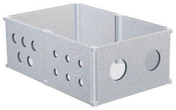

Explosion-proof enclosures of PKIE local control stations can undergo mechanical processing, drilling. Thickness of the walls is sufficient for cutting of thread of various types (to be discussed at order stage) for connection of cable glands of various types. It could be achieved even in relatively small batches, which makes products series KSRV ideal for small- and medium-scale manufacturers which can receive enclosures manufactured in accordance with their requirements and at reasonable price. Upon approval, enclosure covers may have inspection windows for metering instruments and visual inspection devices
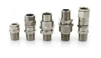
CABLE GLANDS
We manufacture cable glands for all types of connection with various thread types. Wide range of produced cable glands helps to solve multiple tasks of connection of various types of non-armored and armored cables, cables in sheath, flexible conduit and pipe conduit into enclosures of electrotechnical apparatuses.
For full range of cable glands please follow website page "Explosion-proof cable glands"...>>| Size code of cable gland | NPT, GOST 6111 | М, GOST 24705 | PKIE111109 | PKIE141410 | PKIE171109 | PKIE202012 | PKIE301410 | PKIE302314 | PKIE302318 | PKIE513321 | PKIE663221 | PKIE626221 | ||||||||||
| A NPT/М |
B NPT/М |
A NPT/М |
B NPT/М |
A NPT/М |
B NPT/М |
A NPT/М |
B NPT/М |
A NPT/М |
B NPT/М |
A NPT/М |
B NPT/М |
A NPT/М |
B NPT/М |
A NPT/М |
B NPT/М |
A NPT/М |
B NPT/М |
A NPT/М |
B NPT/М |
|||
| 01 | 3/8” | М16Х1,5 | 4/4 | 4/3 | 8/8 | 8/6 | 8/8 | 4/3 | 15/13 | 15/12 | 18/18 | 6/6 | 27/24 | 18/15 | 27/24 | 18/15 |
75/73 | 43/39 | 96/96 | 37/36 | 90/83 | 84/82 |
| 1 | 1/2” | М20Х1,5 | 3/3 | 2/2 | 6/6 | 6/6 | 7/6 | 2/2 | 12/12 | 11/10 | 14/14 | 6/4 | 21/21 | 15/13 | 21/21 |
15/13 |
65/63 | 36/32 | 75/76 | 30/28 | 67/65 | 64/63 |
| 2 | 3/4” | М25Х1,5 | 2/1 | 1/1 | 4/4 | 3/3 | 3/3 | 1/1 | 6/6 | 6/6 | 9/9 | 3/2 | 12/12 | 8/8 | 12/12 |
8/8 |
38/40 | 21/21 | 48/50 | 18/18 | 43/43 | 39/38 |
| 3 | 1” | М32Х1,5 | 1/1 | 1/1 | 2/2 | 2/2 | 2/2 | 1/1 | 5/5 | 5/4 | 6/5 | 2/2 | 10/10 | 6/6 | 10/10 |
6/6 |
27/27 | 15/14 | 36/36 | 13/13 | 33/32 | 31/29 |
| 4 | 1 1/4” | М40Х1,5 | 1/1 | 1/- | 2/1 | 2/1 | 2/2 | 1/- | 3/3 | 3/2 | 4/4 | 1/1 | 5/5 | 3/3 | 5/5 |
3/3 |
14/17 | 8/8 | 20/20 | 8/8 | 18/18 | 18/18 |
| 5 | 1 1/2” | М50Х1,5 | - | - | 1/1 | 1/- | - | - | 2/2 | 2/2 | 3/3 | 1/- | 4/3 | 3/2 | 4/3 |
3/2 |
12/12 | 8/5 | 16/16 | 6/5 | 16/13 | 14/12 |
| 6 | 2” | М63Х1,5 | - | - | 1/1 | - | - | - | 2/1 | 2/1 | - | - | 3/3 | 2/2 | 3/3 |
2/2 |
10/9 | 5/3 | 13/11 | 4/3 | 11/8 | 9/7 |
| 7 | 2 1/2” | М75Х1,5 | - | - | - | - | - | - | 1/1 | - | - | - | 2/2 | 2/1 | 2/2 |
2/1 |
5/5 | 3/3 | 6/6 | 2/2 | 5/5 | 6/6 |
| 8 | 3” | М90Х1,5 | - | - | - | - | - | - | - | - | - | - | - | - | - |
- |
4/4 | 2/2 | 5/5 | 2/2 | 5/5 | 5/5 |
| Previous international name "ZAVOD GORELTEX" Co. Ltd. TU 3400-005-72453807-07 |
The Customs Union name "ZAVOD GORELTEX" Co. Ltd. TU 3400-005-72453807-07 |
| SHORVE111109 | PKIE111109 |
| SHORVE171109 | PKIE171109 |
| SHORVE141410 | PKIE141410 |
| SHORVE202012 | PKIE202012 |
| SHORVE301410 | PKIE301410 |
| SHORVE302310 | PKIE |
| SHORVE302318 | KSRV342421 |
| SHORVE513321 | PKIE513321 |
| SHORVE663220 | PKIE663221 |
| SHORVE626220 | PKIE626221 |
 CAD GoreltEx