
One of the distinct features of GORELTEX explosion-proof products is the ergonomic design of control, indicating and signaling elements. Big size of control elements enables to work in gloves (which is important when working outdoors at low temperatures). Indicating elements have large diameter and are equipped with a reflector which makes the signal clearly visible at large viewing angle and various degrees of surface dirtiness. A wide range of control, indicating and signaling elements of standard version are offered, as well as typical version, upon customer’s request.

To increase the reliability of actuation of buttons in low current systems with switching of minor current and voltage up to 50 mA (12V...5V, 50 mA...1mA); - version of Ex d e IIC U buttons with gold-plated contacts /ST.
Nameplates for buttons and signal lamps are manufactured upon request. The following standard elements may be arranged on the cover of control cabinet enclosure:

 IT IS IMPORTANT TO KNOW
Technical Regulation TR CU 010/2011 "On the safety of machinery and equipment".
Annex 1. General regulations of safety machines and equipment. Clause 15 :
«…Controls devices of a machine and (or) equipment must be constructed so that their form, sizes and contact surfaces of the user correspond to a capture way (fingers, hand) or pressing (hand finger, palm, foot)…»
For the equipment intended for operation at ambient temperatures below zero or in aggressive environment, control elements of the equipment must have the increased size, since the user operates the equipment in protective gloves. It is prohibited to use the control elements that do not meet this requirement.
| Type | Picture | Drawing |
| LGE03... | 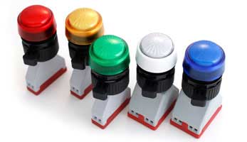 |
Blue White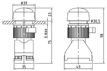 |
Red Green Yellow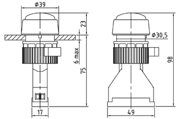 |
| Type | Color | Rated voltage, V | Power consumption, W |
| LGE03K12 | Red | ~/ 12 12 |
>max. 1 |
| LGE03Z12 | Green | ||
| LGE03ZH12 | Yellow | ||
| LGE03S12 | Blue | ||
| LGE03B12 | White | ||
| LGE03K24 | Red | ~/16-36 |
|
| LGE03Z24 | Green | ||
| LGE03ZH24 | Yellow | ||
| LGE03S24 | Blue | ||
| LGE03B24 | White | ||
| LGE03K220 | Red | ~220-380 | |
| LGE03Z220 | Green | ||
| LGE03ZH220 | Yellow | ||
| LGE03S220 | Blue | ||
| LGE03B220 | White |
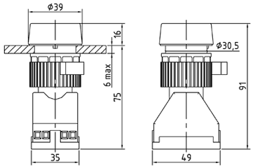
| Type | Picture | Drawing |
| KGE01... |  |
 |
| KGE10... |  |
 |
| Type | Contacts | Color | Rated voltage, V | Rated current, А |
| KGE01K11 | 1NO+1NC | Red | ~120 ~220 ~380 1224110250 |
16 (at ~120 V) 10 (at ~220 V) 6 (at ~380 V) 2 (at 12 V)2 (at 24 V)1 (at 110 V)0,5 (at 250 V) |
| KGE01K20 | 2NO | |||
| KGE01K02 | 2NC | |||
| KGE01K40 | 4NO | |||
| KGE01K31 | 3NO+1NC | |||
| KGE01K22 | 2NO+2NC | |||
| KGE01K13 | 1NO+3NC | |||
| KGE01K04 | 4NC | |||
| KGE01Z11 | 1NO+1NC | Green | ||
| KGE01Z20 | 2NO | |||
| KGE01Z02 | 2NC | |||
| KGE01Z40 | 4NO | |||
| KGE01Z31 | 3NO+1NC | |||
| KGE01Z22 | 2NO+2NC | |||
| KGE01Z13 | 1NO+3NC | |||
| KGE01Z04 | 4NC | |||
| KGE01ZH11 | 1NO+1NC | Yellow | ||
| KGE01ZH20 | 2NO | |||
| KGE01ZH02 | 2NC | |||
| KGE01ZH40 | 4NO | |||
| KGE01ZH31 | 3NO+1NC | |||
| KGE01ZH22 | 2NO+2NC | |||
| KGE01ZH13 | 1NO+3NC | |||
| KGE01ZH04 | 4NC | |||
| KGE01S11 | 1NO+1NC | Blue | ||
| KGE01S20 | 2NO | |||
| KGE01S02 | 2NC | |||
| KGE01S40 | 4NO | |||
| KGE01S31 | 3NO+1NC | |||
| KGE01S22 | 2NO+2NC | |||
| KGE01S13 | 1NO+3NC | |||
| KGE01S04 | 4NC | |||
| KGE01B11 | 1NO+1NC | White | ||
| KGE01B20 | 2NO | |||
| KGE01B02 | 2NC | |||
| KGE01B40 | 4NO | |||
| KGE01B31 | 3NO+1NC | |||
| KGE01B22 | 2NO+2NC | |||
| KGE01B13 | 1NO+3NC | |||
| KGE01B04 | 4NC | |||
| KGE01CH11 | 1NO+1NC | Black | ||
| KGE01CH20 | 2NO | |||
| KGE01CH02 | 2NC | |||
| KGE01CH40 | 4NO | |||
| KGE01CH31 | 3NO+1NC | |||
| KGE01CH22 | 2NO+2NC | |||
| KGE01CH13 | 1NO+3NC | |||
| KGE01CH04 | 4NC | |||
| KGE10K11 | 1NO+1NC | Momentary mushroom button, red | ||
| KGE10K20 | 2NO | |||
| KGE10K02 | 2NC | |||
| KGE10K40 | 4NO | |||
| KGE10K31 | 3NO+1NC | |||
| KGE10K22 | 2NO+2NC | |||
| KGE10K13 | 1NO+3NC | |||
| KGE10K04 | 4NC | |||
| KGE10CH11 | 1NO+1NC | Momentary mushroom button, black |
||
| KGE10CH20 | 2NO | |||
| KGE10CH02 | 2NC | |||
| KGE10CH40 | 4NO | |||
| KGE10CH31 | 3NO+1NC | |||
| KGE10CH22 | 2NO+2NC | |||
| KGE10CH13 | 1NO+3NC | |||
| KGE10CH04 | 4NC |
Version of buttons with gold-plated contacts used for designing of circuits of low current systems - /ST option. Example: KGE01ZH20/ST.
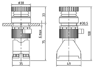
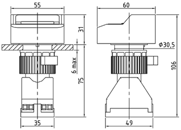
| Type | Picture | Drawing |
| KGE02... |  |
 |
| Type | Contacts | Description | Color | Rated voltage, V |
Rated current, А |
| KGE02KZ11 | 1НО+1НЗ | Momentary double-headed button | Green + red* | ~120 ~220 ~380 1224110250 |
16 (at ~120 V) 10 (at ~220 V) 6 (at ~380 V) 2 (at 12 V)2 (at 24 V)1 (at 110 V)0,5 (at 250 V)
|
| KGE02KZ20 | 2НО | ||||
| KGE02KZ02 | 2НЗ | ||||
| KGE02KZ40 | 4NO | ||||
| KGE02KZ31 | 3NO+1NC | ||||
| KGE02KZ22 | 2NO+2NC | ||||
| KGE02KZ13 | 1NO+3NC | ||||
| KGE02KZ04 | 4NC |
* Buttons with other color combinations may be supplied upon request.
Version of buttons with gold-plated contacts used for designing of circuits of low current systems - /ST option. Example: KGE02KZ20/ST.
| Type | Picture | Drawing |
| KGE06... |  |
 |
| Type | Contacts | Color | Rated voltage of contact block, V | Rated current of contact block, А | Rated voltage of indication, V |
| KGE06K10 | 1NO | Red | ~120 ~220 ~380 1224110250 |
10 (at ~120 V) 10 (at ~220 V) 6 (at ~380 V) 2 (at 12 V)2 (at 24 V)1 (at 110 V)0,5 (at 250 V) |
24-48 ~24-240 |
| KGE06K01 | 1NC | ||||
| KGE06Z10 | 1NO | Green | |||
| KGE06Z01 | 1NC | ||||
| KGE06ZH10 | 1NO | Yellow | |||
| KGE06ZH01 | 1NC | ||||
| KGE06S10 | 1NO | Blue | |||
| KGE06S01 | 1NC | ||||
| KGE06B10 | 1NO | White | |||
| KGE06B01 | 1NC |
| Circuit diagram for KGE06...10 button | Circuit diagram for KGE06...01 button |
 |
 |
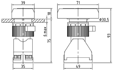
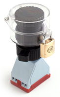
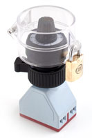
| Type | Picture | Drawing |
| KGE07... |  |
|
| KGE08... |  |
 |
| KGE09... | 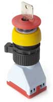 |
 |
| KGE09.../ZSNCH |  |
 |
| Type | Contacts | Description | Color | Rated voltage, V | Rated current, А |
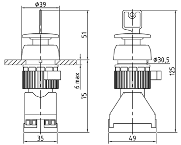
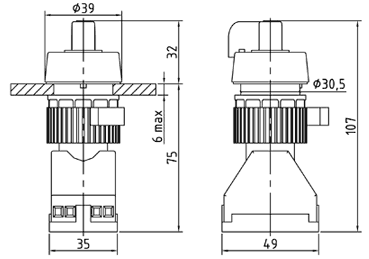
| KGE07K11 | 1NO+1NC | locking mushroom button, unclocking by rotation | Red | ~120 ~220 ~380 1224110250 |
16 (at ~120 V) 10 (at ~220 V) 6 (at ~380 V) 2 (at 12 V)2 (at 24 V)1 (at 110 V)0,5 (at 250 V)
|
| KGE07K20 | 2NO | ||||
| KGE07K02 | 2NC | ||||
| KGE07K40 | 4NO | ||||
| KGE07K31 | 3NO+1NC | ||||
| KGE07K22 | 2NO+2NC | ||||
| KGE07K13 | 1NO+3NC | ||||
| KGE07K04 | 4NC | ||||
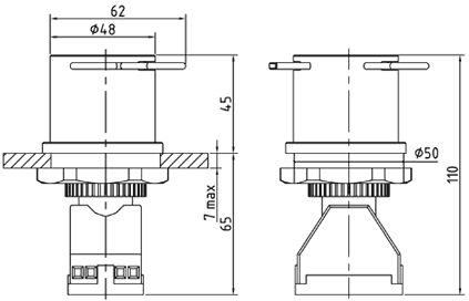
| KGE08K11 | 1NO+1NC | locking mushroom button, unclocking by rotation | Red, with yellow bezel |
||
| KGE08K20 | 2NO | ||||
| KGE08K02 | 2NC | ||||
| KGE08K40 | 4NO | ||||
| KGE08K31 | 3NO+1NC | ||||
| KGE08K22 | 2NO+2NC | ||||
| KGE08K13 | 1NO+3NC | ||||
| KGE08K04 | 4NC | ||||
| KGE09K11 | 1NO+1NC | locking mushroom button, key release | Red, with yellow bezel |
||
| KGE09K20 | 2NO | ||||
| KGE09K02 | 2NC | ||||
| KGE09K40 | 4NO | ||||
| KGE09K31 | 3NO+1NC | ||||
| KGE09K22 | 2NO+2NC | ||||
| KGE09K13 | 1NO+3NC | ||||
| KGE09K04 | 4NC |
Version of buttons with gold-plated contacts used for designing of circuits of low current systems - /ST option. Example: KGE08K02/ST.
| Type | Picture | Drawing |
| PGE1C PGE2I PGE1Z PGE1W |
 |
 |
| PGEZ... |  |
 |
| PGE2S PGE4I PGE2Z |
 |
 |
| PGEPKL | 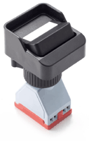 |
 |
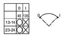
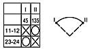
| Type | Contacts | Description | Rated voltage, V | Rated current, А |
|
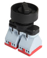
| PGE1C | 2NO | Switch, 3 positions with zero position, diagram 1C |
 |
~120 ~220 ~380 1224110250 |
16 (at ~120 V) 10 (at ~220 V) 6 (at ~380 V) 2 (at 12 V)2 (at 24 V)1 (at 110 V)0,5 (at 250 V) |
| PGE2I | 2NO | Switch, 2 positions, diagram 2I |
 |
||
| PGE1Z | 1NO + 1NC | Switch, 2 positions, diagram 1Z |
 |
||
| PGE1W | 2NO | Switch 3 positions, diagram 1W |
 |
||
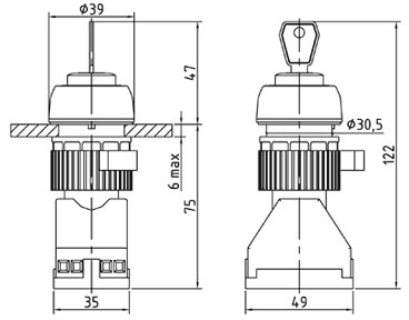
| PGEZ1S | 2NO | Key operated switch, 3 positions. Key is removed in any position of the switch. Diagram 1C |
|
||
| PGEZ2I | 2NO | Key operated switch, 2 positions. Key is removed in any position of the switch. Diagram 2I |
|
||
| PGEZ1Z | 1NO + 1NC | Key operated switch, 2 positions. Key is removed in any position of the switch. Diagram 1Z |
|
||
| PGEZ1W | 2NO | Momentary key operated switch, 3 positions. Key is removed in the medium position of the switch. Diagram 1W |
|
||
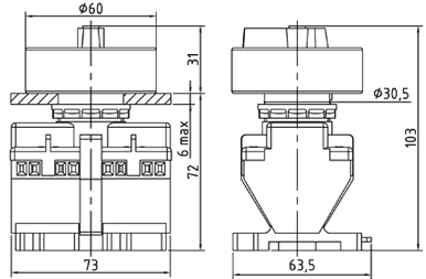
| PGE2S | 4NO | Switch, 3 positions with zero position, diagram 2C |
 |
||
| PGE4I | 4NO | Switch, 2 positions, diagram 4I |
 |
||
| PGE2Z | 2NO + 2NC | Switch, 2 positions, diagram 2Z |
 |
||
| PGEPKL2I | 2NO | Switch, 2 positions, diagram 2I |
 |
||
| PGEPKL1Z | 1NO + 1NC | Switch, 2 positions, diagram 1Z |
 |
||
Version of buttons with gold-plated contacts used for designing of circuits of low current systems - /ST option. Available for types PGE1C, PGE2I, PGE1Z, PGEZ1W. Example: PGE1Z/ST.
| Type | Picture | Drawing |
| PTCE... | 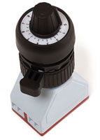 |
 |
| Type | Resistance, Ohm | Power consumption, W |
| PTCE01 | 1 000 | 1 |
| PTCE02 | 2 000 | |
| PTCE03 | 5 000 | |
| PTCE04 | 10 000 |
| Type | Picture | Drawing |
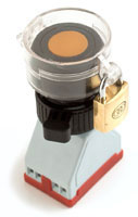
| /ZAMOK1 | 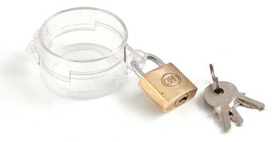 |
 |
| /ZAMOK2 |  |
 |
 |
 |
 |
| Type | Picture | Drawing |
| PSGE01 |  |
 |
| Type | Type of sound signal | Rated voltage, V | Current consumption, А | Sound pressure, dB |
| PSGE01 | Intermittent | 12* |
0,15 | 108 |
* ~220 V version is possible in a ready product.
| Type | Picture | Description |
| M-KIP |  |
Ammeter* |
| Voltmeter* |
* Dimension type, scale, accuracy class and measurement range shall be approved when ordering.
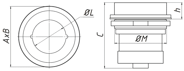
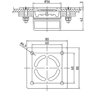
| Name | Dimensions, mm | Mass, kg | |||||
| External | Window size | Hole for installation | |||||
| A | B | C | h | ØL | ØM | ||
| М-KIP-..-48 | 99 | 99 | 107,5 | 27 | 55 | Ø85 | 0,6 |
| М-KIP-..-72 | 139 | 139 | 111,7 | 29,8 | 90 | Ø130 | 1,5 |