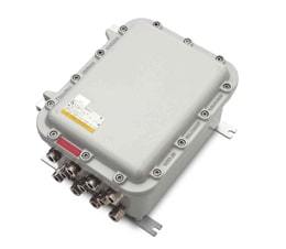
Selection of SHORV (CCFE) type boxes and order placement
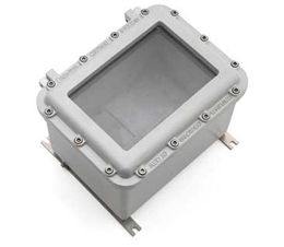
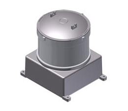
CONFIGURATION OF SHORV BOXES
EXAMPLE 1: SHORV281811(28RP4)-3KOV1N(А)-3KOV1N(C)-TU 3400-005-72453807-07

EXAMPLE 2. SHORV302021(20C2)-KOV2Н(А)-2KOV1N(B)-3KOV1N(C)-2KOV1N(D)-TU 3400-005-72453807-07

EXAMPLE 3. CONFIGURATION OF TWO SHORV BOXES

Boxes may be connected with each other by means of fittings with encapsulation as per GOST 30852.1-2002 (IEC 60079-1:1998)
Main types of terminals used in Exd enclosures*
Type |
Description |
| RN1 |
Screw terminal block 0,2-2,5 sq. mm I=15А
V=600V |
| CBD2 |
Screw terminal block 0,5-4 sq. mm I=24А V=800V
(short marking С) |
| RN2 |
Screw terminal block 0,2-4 sq. mm I=24А V=400V |
| CBD4 |
Screw terminal block 0,5-6 sq. mm I=32А V=800V
(short marking С) |
| RN4 |
Screw terminal block 0,2-6 sq. mm I=32А V=275V |
| CBD6 |
Screw terminal block 0,5-10 sq. mm I=41А V=800V
(short marking С) |
| CBD10 |
Screw terminal block 0,5-16 sq. mm I=57А V=800V
(short marking С) |
| CBD16 |
Screw terminal block 0,5-25 sq. mm I=76А V=800V
(short marking С) |
| CBD35 |
Screw terminal block 0,5-35/50 sq. mm I=125А
V=800V (short marking С) |
| CBD50 |
Screw terminal block 1,5-50/70 sq. mm I=150А
V=800V (short marking С) |
| CBD70 |
Screw terminal block 1,5-95 sq. mm I=192А
V=800V (short marking С) |
| CDА120 |
Screw terminal block 4-150/185 sq. mm I=269А
V=800V (short marking С) |
| CDА185 |
Screw terminal block 4-240 sq. mm I=353А
V=800V (short marking С) |
| GPM95BB |
Screw terminal block busbar+busbar up to 22 mm
wide (М8 bolt) I=232А V=1000V |
| GPM150BB |
Screw terminal block busbar+busbar up to 32 mm
wide (М10 bolt) I=309А V=1000V |
| GPM240BB |
Screw terminal block busbar+busbar up to 40 mm
wide (М12 bolt) I=415А V=1000V |
| GPM95BC |
Screw terminal block
busbar (up to 22 mm wide,
М8 bolt) + wire 25-120 sq.mm I=232А
V=1000V |
| GPM150BC |
Screw terminal block
busbar (up to 32 mm wide,
М10 bolt) + wire 35-185 sq. mm I=309А
V=1000V |
| GPM240BC |
Screw terminal block
busbar (up to 40 mm wide,
М12 bolt) + wire 50-300 sq. mm I=415А
V=1000V |
| GPM95CC |
Screw terminal block
wire+wire 25-120 sq. mm
I=232А V=1000V |
| GPM150CC |
Screw terminal block
wire+wire 35-185 sq. mm
кв. I=309А V=1000V |
| GPM240CC |
Screw terminal block
wire+wire 50-300 sq. mm I=415А V=1000V |
| UT2 |
Screw terminal block 0,5-4 sq. mm I=28А V=750V |
| UT4 |
Screw terminal block 0,5-6 sq. mm I=38А V=750V |
| UT6 |
Screw terminal block 0,5-10 sq. mm I=50А V=750V |
| UT10 |
Screw terminal block 0,5-16 sq. mm I=69А V=750V |
| HMM1 |
Spring terminal block 0,2-2,5 sq. mm I=17,5А
V=500V |
| HMM2 |
Spring terminal block 0,2-4 sq. mm I=24А
V=800V |
| HMM4 |
Spring terminal block 0,2-6 sq. mm I=32А
V=800V |
| HMM6 |
Spring terminal block 0,2-10 sq. mm I=41А
V=800V |
| ТE2 |
Screw terminal block 0,5-4 sq. mm ground |
| ТE4 |
Screw terminal block 0,5-6 sq. mm ground |
| ТE6 |
Screw terminal block 0,5-10 sq. mm ground |
| ТE10 |
Screw terminal block 0,5-16 sq. mm ground |
| ТE16 |
Screw terminal block 0,5-25 sq. mm ground |
| ТE50 |
Screw terminal block 1,5-50/70 sq. mm ground |
| ТE70 |
Screw terminal block 1,5-95 sq. mm ground |
*Application of screw and spring terminals is possible:
CBD, DAS, HMM, TE, RN, RP, TR, CDA, SV, PCE, DT, QTC, MZB, EDM, ST,
UT,
WDU, WDK, ZDU, ZDK, WPE, SAK, AKZ, BPL, TPL, SK, UKN
and A ground elements, as well as other types of terminals and busbars upon customer‘s request. |
Main types of circuit breakers used in Exd enclosures**
Type
| Description |
| A1/6 |
Circuit breaker 1 pole I=6A |
| A1/10 |
Circuit breaker 1 pole I=10A |
| A1/16 |
Circuit breaker 1 pole I=16A |
| A1/20 |
Circuit breaker 1 pole I=20A |
| A1/25 |
Circuit breaker 1 pole I=25A |
| A1/32 |
Circuit breaker 1 pole I=32A |
| A1/40 |
Circuit breaker 1 pole I=40A |
| A1/63 |
Circuit breaker 1 pole I=63A |
| A1/80 |
Circuit breaker 1 pole I=80A |
| A1/100 |
Circuit breaker 1 pole I=100A |
| A1/125 |
Circuit breaker 1 pole I=125A |
| A1/150 |
Circuit breaker 1 pole I=150A |
| A1/250 |
Circuit breaker 1 pole I=250A |
| A1/400 |
Circuit breaker 1 pole I=400A |
| A2/6 |
Circuit breaker 2 poles
I=6A |
| A2/10 |
Circuit breaker 2 poles I=10A |
| A2/16 |
Circuit breaker 2 poles I=16A |
| A2/20 |
Circuit breaker 2 poles I=20A |
| A2/25 |
Circuit breaker 2 poles I=25A |
| A2/32 |
Circuit breaker 2 poles I=32A |
| A2/40 |
Circuit breaker 2 poles I=40A |
| A2/63 |
Circuit breaker 2 poles I=63A |
| A2/80 |
Circuit breaker 2 poles I=80A |
| A2/100 |
Circuit breaker 2 poles I=100A |
| A2/125 |
Circuit breaker 2 poles I=125A |
| A2/150 |
Circuit breaker 2 poles I=150A |
| A2/250 |
Circuit breaker 2 poles I=250A |
| A2/400 |
Circuit breaker 2 poles I=400A |
| A3/6 |
Circuit breaker 3 poles I=6A |
| A3/10 |
Circuit breaker 3 poles I=10A |
| A3/16 |
Circuit breaker 3 poles I=16A |
| A3/20 |
Circuit breaker 3 poles I=20A |
| A3/25 |
Circuit breaker 3 poles I=25A |
| A3/32 |
Circuit breaker 3 poles I=32A |
| A3/40 |
Circuit breaker 3 poles I=40A |
| A3/63 |
Circuit breaker 3 poles I=63A |
| A3/80 |
Circuit breaker 3 poles I=80A |
| A3/100 |
Circuit breaker 3 poles I=100A |
| A3/125 |
Circuit breaker 3 poles I=125A |
| A3/150 |
Circuit breaker 3 poles I=150A |
| A3/250 |
Circuit breaker 3 poles I=250A |
| A3/400 |
Circuit breaker 3 poles I=400A |
| A4/6 |
Circuit breaker 4 poles I=6A |
| A4/10 |
Circuit breaker 4 poles I=10A |
| A4/16 |
Circuit breaker 4 poles I=16A |
| A4/20 |
Circuit breaker 4 poles I=20A |
| A4/25 |
Circuit breaker 4 poles I=25A |
| A4/32 |
Circuit breaker 4 poles I=32A |
| A4/40 |
Circuit breaker 4 poles I=40A |
| A4/63 |
Circuit breaker 4 poles I=63A |
| A4/80 |
Circuit breaker 4 poles I=80A |
| A4/100 |
Circuit breaker 4 poles I=100A |
| A4/125 |
Circuit breaker 4 poles I=125A |
| A4/150 |
Circuit breaker 4 poles I=150A |
| A4/250 |
Circuit breaker 4 poles I=250A |
| A4/400 |
Circuit breaker 4 poles I=400A |
**Installation of other elements of automation systems in Exd enclosures is possible. |
Maximum permitted number of installed CBD terminals (not taking into account the installation of cable glands)
| Enclosure size |
Number of terminals /nominal wire cross-section, mm2 |
| 2,5 |
4 |
6 |
10 |
16 |
35 |
50 |
70 |
| Max. number |
Max. number |
Max. number |
Max. number |
Max. number |
Max. number |
Max. number |
Max. number |
| SHORV281811 |
31 |
26 |
21 |
17 |
14 |
10 |
9 |
3 |
| SHORV302021 |
56 |
48 |
24 |
20 |
16 |
10 |
9 |
6 |
| SHORV422221 |
100 |
84 |
68 |
54 |
23 |
17 |
15 |
13 |
| SHORV362827 |
117 |
99 |
78 |
44 |
35 |
26 |
20 |
16 |
| SHORV362821 |
| SHORV423229 |
150 |
126 |
102 |
81 |
54 |
40 |
34 |
20 |
| SHORV423222 |
| SHORV464621 |
245 |
208 |
168 |
136 |
112 |
54 |
48 |
32 |
| SHORV573931 |
300 |
252 |
204 |
120 |
99 |
54 |
48 |
42 |
| SHORV573926 |
| SHORV654533 |
344 |
292 |
236 |
188 |
156 |
87 |
78 |
50 |
| SHORV654526 |
| SHORV725235 |
424 |
356 |
288 |
212 |
176 |
99 |
90 |
56 |
| SHORV725224 |
| SHORV896745 |
508 |
432 |
348 |
280 |
232 |
120 |
105 |
93 |
| SHORV896735 |
* Values given in the table are similar to those for SHORV enclosures with window and SHORV-N enclosures
CABLE GLANDS
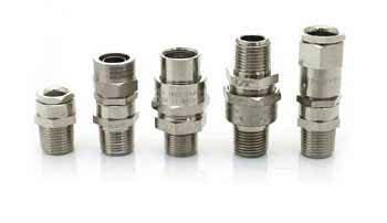 For direct insertion of cables and wires to Exd enclosure, specially developed Exd glands for direct insertion are applied. According to the mandatory requirements, this characteristic is specified in the certificate. This helps to refuse from inlet junction box (except for mining version РВ), which makes the products of "ZAVOD GORELTEX" Co. Ltd. unique compared with products of other companies.
Wide range of produced cable glands helps to solve multiple tasks of connection of various types of non-armored and armored cables, cables in sheath, flexible conduit and pipe conduit into enclosures of electrotechnical apparatuses.
Due to material of construction and special coating, our cable glands can be used in moist and dusty rooms and in highly aggressive ambient conditions. Cable glands are resistant to salt spray and other chemical substances, including hydrogens sulfide and hydrochloric acid vapors, saline and acidic mine waters. For full range of cable glands please follow website page "Explosion-proof cable glands". Interactive selection of an explosion-proof cable gland...>>
Table of selection of SHORV, SHORVA boxes and enclosures for application in various branches of industry and cost of product*
Enclosure type |
SHORV |
SHORVA |
SHORV-N |
Increasing of the product cost |
Low > High |
Pharmaceutical plants, indoor installation |
5 |
5 |
5 |
Chemical plants, indoor installation |
4 |
5 |
5 |
Chemical plants, outdoor installation |
5 |
5 |
5 |
Milling plants, indoor installation |
5 |
4 |
inappropriate |
Milling plants, outdoor installation |
5 |
5 |
inappropriate |
Paint manufacturing plants, indoor/outdoor installation |
5 |
5 |
inappropriate |
Gas storage tanks, indoor/outdoor installation |
5 |
5 |
inappropriate |
Wastewater treatment plants, indoor/outdoor installation |
5 |
5 |
5 |
Vessel terminals, indoor/outdoor installation |
5 |
5 |
5 |
Piers and vessel decks, indoor/outdoor installation |
5 |
5 |
5 |
Oil loading terminals, indoor/outdoor installation |
5 |
5 |
5 |
Offshore oil and gas platforms, indoor installation |
5 |
5 |
5 |
Offshore oil and gas platforms, outdoor installation |
5 |
5 |
5 |
Nuclear power plants |
5 |
5 |
5 |
5 perfectly fit with long service life
4 meets expectations of reasonable service life
*Note:
- The table shows corrosion resistance of the enclosure material, its resistance to exposure caused by pollution, as well as ingress protection degree.
- When choosing the enclosure it is important to take into account the ambient environment where the box will be operated. It is especially important for enclosures which are used in hazardous areas, since the enclosure is the essential component of protection. The attention should be particularly paid to the consequences of the corrosion and presence of chemical substances in the atmosphere, as well as probable mechanical impact.
| |
Cast iron/steel |
Plastic |
Stainless steel 08Х18Н10 |
GORELTEX stainless steel* |
Aluminum alloy
(copper >0,1%, iron>0,7%,
magnesium >0,1%) |
GORELTEX aluminum alloy ** |
| Average service life of enclosure, years |
20 |
4 |
25 |
30 |
5 |
25 |
| Flameproof joint service life, years |
Outdoor installation |
3 |
- |
15 |
30 |
2 |
20 |
| Indoor installation |
5 |
3 |
20 |
30 |
4 |
25 |
Reconditioning (grinding) of flameproof joint
|
+ |
- |
- |
- |
- |
- |
|
Cost of enclosures production
|
low |
average |
high |
high |
low |
average |
| Cost of Ex components installation |
high |
low |
very high |
very high |
average |
low |
| Possible dimensions of enclosures |
large |
small |
large |
large |
average |
large |
| Mass of enclosures |
heavy |
small |
heavy |
heavy |
average |
small |
| Dissipated power |
high |
low |
average |
average |
maximum |
maximum |
| Application in marine conditions |
- |
- |
+ |
+ |
- |
+ |
*Corrosion-resistant stainless chrome-nickel cast steel of "ZAVOD GORELTEX" Co. Ltd.
**Modified corrosion-resistant aluminum alloy (copper ≤ 0,1%, iron ≤ 0,4%, magnesium ≤ 0,1%) of "ZAVOD GORELTEX" Co. Ltd.
Flameproof joint service life defines the duration of use of Exd enclosures in a hazardous area.
OPTIONS, ACCESSORIES AND VERSIONS
ORDER CREATION
Radiator cooling system
/RADIATOR
Captive bolts for cover fastening
/NBK
Ingress protection degree IP67
/IP67
Heating for automation
/OBOGREV
Internal thermal insulation
/TEPLOIZOLJCIJA
Aluminum alloy mounting panel
/ALP
Marking of terminals as per customer’s diagram
/MARK
Terminal jumpers as per customer’s diagram
/SHEMA
Internal ground bus bar
/SHINA Z
Device for connection of cable screens
/JEKRAN
External surface coating as per customer’s specification
/RAL (___)
Stainless steel mounting plate
/NP
Anti-condensation coating
/AP
Nameplate with inscription as per customer’s specification
/NADPIS "_"
Acceptance by customer
/PRIEMKA
Earthquake-resistant version
/MSK-64
Version for nuclear facilities
/MALAJA TECH
Version for tropics with protection against bugs
/TERMITY
Version for minimum operating temperature -75°C
/HOLOD
Breather plug for moisture removal
/VKU
Drain plug for condensate removal
/DKUV
Cover fixation on hinges
/PETLJА
Mine normal execution
/RN
Note: bus bars having 2 holes x 16 mm2 and a row of holes 6 mm2 (number depends on the bus bar length) are installed by default for options /SHINA G and /SHINA N. Installation of bus bars with another diameter of holes is possible upon customer‘s approval.
FORMATION OF ORDER
| SHORV |
|
Х |
- ( |
Х |
|
Х |
- |
Х |
|
Х |
) - |
Х |
|
Х |
( |
Х |
) - |
Х |
|
Х |
( |
Х |
) / |
Х |
– TU 3400-005-72453807-07 |
|
|
|
|
|
|
|
|
|
|
|
|
|
|
|
|
|
|
|
|
|
|
|
|
|
|
| |
|
|
|
|
|
|
|
|
|
|
|
|
|
|
|
|
|
|
|
|
|
|
|
|
Product name |
| |
|
|
|
|
|
|
|
|
|
|
|
|
|
|
|
|
|
|
|
|
|
|
|
|
Size code |
| |
|
|
|
|
|
|
|
|
|
|
|
|
|
|
|
|
|
|
|
|
|
|
|
|
Number of terminals |
| |
|
|
|
|
|
|
|
|
|
|
|
|
|
|
|
|
|
|
|
|
|
|
|
|
Type of terminal |
| |
|
|
|
|
|
|
|
|
|
|
|
|
|
|
|
|
|
|
|
|
|
|
|
|
Number of cable glands |
| |
|
|
|
|
|
|
|
|
|
|
|
|
|
|
|
|
|
|
|
|
|
|
|
|
Type of cable gland |
| |
|
|
|
|
|
|
|
|
|
|
|
|
|
|
|
|
|
|
|
|
|
|
|
|
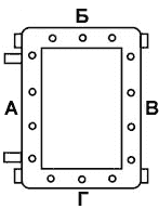
Side of cable gland location |
| |
|
|
|
|
|
|
|
|
|
|
|
|
|
|
|
|
|
|
|
|
|
|
|
|
Options, accessories and versions |
Example: SHORV362821 (40C2 - 10C16) - 5KNV1N(B) - 2KNV4N(D)- TU 3400-005-72453807-07
If you find it difficult to select the box size in accordance with required characteristics, just put Xs instead of digits after box name:
Example: SHORV Х (40C2 - 10C16) - 5KNV1N(B) - 2KNV4N(D)- TU 3400-005-72453807-07

 GoreltEx computer-aided design system
 Calculation of heater power for heated cabinet